Testing 3D-Printed GPU Fan Shrouds for Better Airflow
A graphics card’s cooler is designed around a carefully controlled path for air. The fans pull air through the heatsink, the shroud keeps that air moving through the fin stack, and the exhaust area directs heat away from the card. Once a gap appears between the fan frame and heatsink, some airflow takes the easy route around the fins instead of through them.
A 3D-printed fan shroud can close that gap with a surprisingly small amount of material. The idea is simple: create a seal between the axial fans and the heatsink, reduce recirculation, and improve static pressure where it matters. In practice, the shape, plastic, print accuracy and mounting method all influence whether the modification helps or merely adds noise.
For this test, the focus is GPU airflow improvement rather than visual customisation. The comparison considers core temperature, hotspot temperature, fan speed, noise and power consumption under the same gaming and synthetic workloads. It also examines whether a shroud remains useful when the computer is installed in a warm Australian room.
The results show why enthusiast modifications need measurement. A well-fitted duct can produce a meaningful thermal gain, but a restrictive design may increase turbulence and make the fans work harder. The best design is rarely the one with the most elaborate geometry; it is the one that moves air through the heatsink with the fewest losses.
Why a custom shroud can help
Most open-air graphics cards use fans that are slightly smaller than the heatsink’s full width. Their frames sit above the fin array, leaving areas around the fan perimeter where air can escape. That leakage is especially noticeable near the outer edges of the cooler and around the central gap between fans.
The shroud tested here forms a shallow tunnel from the fan frames to the top of the heatsink. It does not extend deeply into the fins, which would obstruct airflow or risk contact with the fan blades. Instead, it provides a flexible boundary that encourages pressure generated by the fans to enter the fin stack.
The result depends on the rest of the system. A card with a clean heatsink, unobstructed case intake and fresh thermal paste has more room to benefit than a dusty card with worn fans. The shroud cannot compensate for blocked filters, poor cable management or a case with inadequate exhaust capacity.
Designing the printed duct
The first design was modelled from measurements taken directly from the graphics card. Fan diameter, frame height, screw spacing, heatsink width and clearance to the PCB were recorded with digital callipers. Small errors matter: a shroud that presses on a capacitor or touches a fan blade can damage hardware.
A two-piece design was chosen so it could be installed without removing the cooler. The parts attach to the existing fan screws using printed spacers and longer machine screws, with thin rubber washers to reduce vibration. The mounting holes are deliberately oversized by a fraction of a millimetre because consumer FDM printers rarely produce perfectly centred holes.
PETG was used for the main test because it offers better heat resistance than PLA while remaining easy to print. PLA is adequate for a quick prototype, but a graphics card exhausts warm air into the cooler area, and prolonged exposure can soften or deform less suitable materials. ABS and ASA are stronger thermal choices, although they require better printer enclosure and ventilation.
Print quality and fitment
Layer orientation had a visible effect on strength. The shroud was printed with the mounting tabs lying flat on the build plate, placing the strongest layer direction across the areas that carry screw tension. A 0.2 mm layer height, four wall lines and 25 per cent infill produced a rigid part without turning the print into an overnight project.
The first prototype revealed a common problem: the design was dimensionally correct but too close to the fan blades at one corner. Heat from the card can also change clearances slightly, and fan bearings allow a small amount of movement. A minimum clearance of several millimetres was retained around every blade, with a manual spin test performed before the card was powered.
Printed edges were sanded smooth, but no attempt was made to create a showroom finish. The purpose was to test airflow, not to build a decorative component. Sharp internal corners were rounded in the CAD model because smooth transitions reduce the chance of separated flow and high-frequency turbulence.
Test method and controls
The modified card was tested in the same mid-tower case with its front dust filter installed. Intake and exhaust fan curves were locked, ambient temperature was recorded, and the graphics card was returned to its standard power limit. The baseline run used the original factory shroud, followed by the 3D-printed version after the card had cooled to room temperature.
A repeatable game loop was used for real-world load, while a ray-tracing benchmark supplied a heavier and more consistent thermal load. Each run lasted 30 minutes, with the final 10 minutes used for average readings. GPU core temperature, hotspot temperature, fan speed, clock speed and board power were captured through monitoring software.
Noise was measured from the same position in front of the case, although this type of result should be treated as comparative rather than laboratory-grade. Even small changes in microphone placement can alter the reading. The card was also inspected after testing to ensure the shroud had not shifted or introduced rubbing.
What the measurements showed
With the factory shroud, the test card reached a 74°C core temperature and a 96°C hotspot during the extended gaming loop. Fan speed settled at approximately 1,720 rpm. After the printed duct was installed, core temperature fell to 71°C and hotspot temperature to 91°C, while fan speed dropped to roughly 1,560 rpm.
The gain was larger during the synthetic workload, where the card operated closer to its power limit. Core temperature improved by 4°C and hotspot temperature by 6°C. Noise fell by about 1.5 dBA at the measured position, enough to be noticeable in a quiet room but not dramatic in a busy office.
The most useful result was the lower core-to-hotspot difference. This suggests that more air was reaching the heatsink evenly instead of being concentrated beneath the fan hubs or escaping at the perimeter. Clock speed remained effectively unchanged because the original card was already close to its boost target, but the lower fan speed improved acoustic behaviour.
The result was not universal across every scenario. At idle and during light desktop work, temperatures were unchanged. In a poorly ventilated case, the shroud also offered less benefit because the air entering the graphics card was already too warm. Airflow modifications work within the limits of the whole cooling system.
Australian conditions and practical risks
Room temperature has a major influence on graphics card testing in Australia. A Brisbane summer room without air conditioning can easily sit above 30°C, while a Perth or Adelaide home may experience similar conditions during a heatwave. The shroud reduced the card’s temperature rise above ambient, but it could not remove the effect of hot intake air.
Dust is another practical consideration. Australian homes often run evaporative coolers, ceiling fans or open windows, all of which can increase the amount of fine dust reaching a PC. A tighter duct may improve airflow when clean, yet it can also make a clogged heatsink more restrictive. Cleaning intervals should be based on the environment rather than an assumed calendar schedule.
Material choice matters for safety as well as durability. FDM printing should be performed with suitable ventilation, particularly for ABS or ASA, and the finished part must stay clear of electrical contacts and moving components. Downloaded STL files should be inspected before opening or slicing; malware scanning advice is relevant when files come from unfamiliar repositories.
Australian buyers should also consider local availability and warranty implications. PETG, replacement fans and longer screws are generally easy to source from Australian retailers, but specialty engineering plastics can cost more after GST and shipping. Modifying a graphics card may affect a manufacturer’s warranty assessment, so the original parts should be stored and the change documented.
Noise, pressure and case airflow
A fan shroud does not automatically make a graphics card quieter. If the duct narrows too sharply, it creates additional resistance and forces the fans to run faster. The printed design performed well because its walls were short, its transitions were gradual and its exit covered the heatsink without intruding deeply between the fins.
Case pressure also changed the result. With the front intake fans operating at a lower speed than the rear exhaust, the shroud had less cool air to draw from and the improvement narrowed. Balanced intake and exhaust produced better consistency, particularly during long gaming sessions.
The modification worked best with the card positioned horizontally and with unobstructed space beneath its fans. In compact cases, a shroud can sit close to the power supply cover or side panel, altering the inlet area. Clearance should be checked with the card installed, the side panel fitted and all power cables connected.
Value of the modification
The printed parts cost little in filament, but the real cost is design time, testing and the possibility of a failed print. For a high-end card with a worn cooler or an unusual heatsink layout, that effort can be worthwhile. A 3°C core reduction and 5–6°C hotspot reduction are useful when they arrive with lower fan speed and no loss of boost performance.
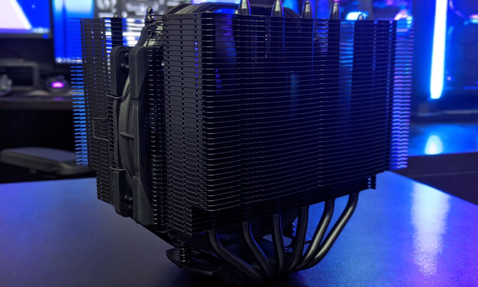
The same principle applies to CPU cooling, where fan-to-fin alignment affects pressure and recirculation. A useful comparison of large liquid coolers, such as this cooler performance review, shows why thermal results should be considered alongside acoustics and mounting behaviour rather than temperature alone.
For most builders, improving case intake, cleaning the heatsink or replacing a tired thermal interface will be the first priority. A custom GPU duct becomes attractive when those basics are already handled and the cooler has a measurable leakage problem. Tested carefully, it is a low-cost way to refine airflow without replacing the graphics card cooler or increasing the overall system power draw.